Sunday, September 21, 2014

Automatic Load Sensing Power Switch

This circuit will automatically switch on several mains-powered "slave" loads when a "master" load is turned on. For example, it will switch on the amplifier and CD player in a stereo system when the receiver is turned on. It works by sensing the current draw of the "master" device through a low value high wattage resistor using a comparator. The output of that comparator then switches on the "slave" relay. The circuit can be built into a power bar, extension cord or power center to provide a convenient set of "smart" outlets that switch on when the master appliance is powered (turn on the computer monitor and the computer, printer and other peripherals come on as well).

Automatic Load Sensing Power Switch Circuit diagram


Parts List 
 Part            


  Total Qty.


Description


C1, C3               2               10uF 35V Electrolytic Capacitor
C2     1               1uF 35V Electrolytic Capacitor
R1     1               0.1 Ohm 10W Resistor
R2     1               27K 1/2W Resistor
R3, R4     1               1K 1/4W Resistor
R5     1               470K 1/4W Resistor
R6     1               4.7K 1/2W Resistor
R7     1               10K 1/4W Resistor
D1, D2, D4     3               1N4004 Rectifier Diode
D3     1               1N4744 15V 1 Watt Zener Diode
U1     1               LM358N Dual Op Amp IC
Q1     1               2N3904 NPN Transistor
K1     1               Relay, 12VDC Coil, 120VAC 10A Contacts
S1     1               SPST Switch 120AVC, 10A
MISC     1               Board, Wire, Socket For U1, Case, Mains Plug, Socket

 Notes
  • This circuit is designed for 120V operation. For 240V operation, resistors R2 and R6 will need to be changed. 
  • A maximum of 5A can be used as the master unless the wattage of R1 is increased S1 provides a manual bypass switch.
  • THis circuit is not isolated from the mains supply. Because of this, you must exercise extreme caution when working around the circuit if it is plugged in.
Read More..

Saturday, September 20, 2014

USB Keyboard Made from Old Typewriter

Looking for a unique gift? Here’s an antique typewriter which has been modified to function as a USB Keyboard for PC, Mac, or even iPad. That’s very cool, isn’t it?

Hacks

In the world of obsolescence, this USB typewriter is a groundbreaking innovation. It does not change the outward appearance of the typewriter and is easy to install since there is no messy wiring. The 3 components of the USB typewriter are the Sensor board, the USB switches, and the Reed Switches.

It works like a regular typewriter with all letters, numerals, and punctuation marks as well as shift, space, and return carriage. It’s a better addition to your home office.


Read More..

Voltage Limiter For Guitar Amplifiers

Guitar amplifiers using output devices such as the TDA7293 (100 W) or LM3886 (68 W) are surprisingly often damaged as a result of excessive supply voltage in the quiescent state. The transformers are often used so close to their specification that this problem can even be caused by a high mains input voltage. In most countries the domestic AC outlet voltage is permitted to rise as high 10 % above the nominal (published) value. Since replacing the transformer is not an attractive proposition, the author developed a relatively simple electronic solution to the overvoltage problem: a voltage limiter for the symmetric supply to the amplifier. The circuit is based on the classical voltage regulator arrangement of a Zener diode connected to the base of a pass transistor.

However, in this version we replace the conventional bipolar transistor with a power MOSFET. The circuit is symmetrical with respect to the negative and positive supplies, and so we shall only describe the positive half. The input voltage (at most 50 V) supplies the chain of Zener diodes D1, D2 and D3 via resistor R3. The resistor limits the current through the Zener diodes to about 5mA. The series connection of Zener diodes has the advantage that their dissipation is divided among them, as well as giving more options for the total voltage drop by judicious selection of individual components. The sum of the diode voltages (39 V with the values given) must be greater than the desired limiting output voltage by the gate-source voltage of the MOSFET.

Circuit diagram:Voltage


C1 smooths the voltage across the Zener diode chain. The circuit therefore not only limits the voltage, but also reduces the ripple (hum component) on the supply. The gate of the HEXFET is driven via R1. In conjunction with C4, this prevents the FET from oscillating. Without any load the output voltage is rather higher than expected. With a small load, such as that presented by the output stage in its quiescent state, it falls to the desired value. The circuit then does not provide regulation of the output voltage, but rather a stabilization function. The operation of the negative half of the circuit is identical to that of the positive half apart from the polarity of the voltages, and hence a P-channel MOSFET must be used there.

It is worth noting that there is a relatively large degree of variation (up to a few volts) in the gate-source voltage of the HEXFETs used. This can be compensated for by selecting the Zener diodes in the chain and the current through them, but for most applications the exact voltage at which limiting begins to occur will not be critical. The HEXFETs must be provided with adequate cooling. If possible, they can be attached to the heatsink already present in the amplifier; otherwise, a separate heatsink will be required. A thermal rating of 2.5 K/W will be suitable.

Author: Alfred Rosenkränzer (Germany) - Copyright: Elektor Electronics 2011
Read More..

Fuse Box BMW 325iX 90 Diagram

Fuse Box BMW 325iX 90 Diagram - Here are new post for Fuse Box BMW 325iX 90 Diagram.

Fuse Box BMW 325iX 90 Diagram


Fuse
Fuse

Fuse Panel Layout Diagram Parts: unloader relay, high speed relay, fog light relay, high beam relay, low beam relay, normal speed relay, horn relay.
Read More..

Explanation Fuse Box Chevrolet Corvette Engine Compartment 2011 DIagram

Fuse Box Chevrolet Corvette Engine Compartment 2011 DIagram - This show you about Fuse Box Chevrolet Corvette Engine Compartment 2011 DIagram.

Fuse Box Chevrolet Corvette Engine Compartment 2011 DIagram


Fuse
Fuse

Fuse Panel Layout Diagram Parts: Transmission control module / transmission, Horn, alternator sense, Antilock braking system (ABS) / real time damping, Wiper, Stop lamps/Back-up lamps, Oxygen sensor, Battery main, Parking lamps, Powertrain relay input/Electronic throttle control, Manual transmission solenoids, Antilock braking systems, Odd numbered fuel injectors, Electronic suspension control, Canister purge solenoid, mass air flow sensor, Air conditioner compressor, Even numbered fuel injectors, Windshield washer, Headlamp washer, Passenger-side low-beam headlamp, Fuel pump, Driver side low-beam headlamp, Front fog lamp, Passenger side high-beam headlamp, Driver side high-beam headlamp, Engine control module.
Read More..

Fuse Box Toyota 2000 MR2 Spyder Engine Compartment Diagram

Fuse Box Toyota 2000 MR2 Spyder Engine Compartment Diagram - Here are new post for Fuse Box Toyota 2000 MR2 Spyder Engine Compartment Diagram.

Fuse Box Toyota 2000 MR2 Spyder Engine Compartment Diagram


Fuse
Fuse

Fuse Panel Layout Diagram Parts: horn, hazard lamp, EFI, head lamp, main relay, heater, ignition coil, daytime running light, radio, alternator.
Read More..

Friday, September 19, 2014

Fuse Box Toyota 1987 Camry Diagram

Fuse Box Toyota 1987 Camry Diagram - Here are new post for Fuse Box Toyota 1987 Camry Diagram.

Fuse Box Toyota 1987 Camry Diagram


Fuse
Fuse

Fuse Panel Layout Diagram Parts: Head light relay, EFI main relay, Charge, Engine main relay, RDI Fan relay, A/C Fan Relay, A/C Magnet clutch relay, Radio, Headlamp, EFI, Haz-horn.
Read More..

Absolute Value Meter With Polarity Detector

This circuit breaks an input voltage signal down into its components: (1) the absolute value and (2) the polarity or ‘sign’ (+ or –). It will handle direct input voltages as well as alternating voltages up to several kHz. With a supply voltage of ±9 V, the input level should remain below ±6V. The circuit consists of two sections, each having its own function. Operational amplifiers IC1a and IC1b form a full-wave rectifier, its output terminal supplying the absolute value of the input signal, while operational amplifiers IC1c and IC1d examine the polarity of the input voltage. For negative input voltages, the output of IC1a goes high.

Consequently D2 is reverse-biased so that IC1a has no effect on the rest of the circuit. IC1b then acts as an inverter because its amplification is (–R5/R3) or –1. Thus, the output voltage is positive. For positive input voltages, D2 conducts and the amplification of IC1a is -1. The output voltage is then determined by the sum of currents that flow through R3 and R4. Taking into account the polarities and the value of all resistors, the overall amplification becomes

–R5/R3 + (–R5/R4) ↔ (–R2/R1) = –1 + 2 = 1

This means that the value of the output voltage at the output terminal is the same as the input voltage, but the polarity is always positive. The accuracy of the rectification process is determined by the accuracy of resistors R1-R4; close-tolerance (1%) types are recommended. At low input voltages (smaller than 20 mV), the input offset voltage of the operational amplifiers may introduce significant errors. If this is the case, use individual operational amplifiers instead of an array of four (TL061, TLC271, AD548, ...), because they have pins for offset voltage compensation. Alternatively, use an operational amplifier with a low offset voltage like the OP07. In the polarity detector IC1c acts as a comparator, with a certain amount of positive feedback due to R7 and R8.

Absolute-ValueThis feedback causes a hysteresis of 20mV that prevents oscillation when the input voltage changes slowly. IC1d is an ordinary inverter. For input voltages above 10mV, the SIGN output terminal will swing to almost the positive supply. When the input voltage is below –10mV, the SIGN terminal drops low, almost to the negative supply voltage. For input voltages between these two thresholds, the output voltage is well defined, too, because it stays at its previous level. This circuit is the perfect complement to the ‘+/– voltage on bargraph display’ circuit discussed elsewhere in this blog.

The |Uin| and SIGN outputs of the present circuit may be directly connected to Uin and CONTROL IN inputs of the bi-directional bar display. The ±6 V sign indicator signal may be used as the control voltage for the +/– voltage display as long as the reference voltage remains smaller than 3 V. Although presented as a pair, both circuits may of course be used individually for other purposes.
Read More..

Mercedes Explanation Fuse Box Year 2001 W211 Diagram

Fuse Box Mercedes 2001 W211 Diagram - Below is Fuse Box Mercedes 2001 W211 Diagram.

Fuse Box Mercedes 2001 W211 Diagram


Fuse
Fuse

Fuse Panel Layout Diagram Parts: servo magnet, armature, front cover, ignition control module position sensor, camshaft sprocket, washer, collar bolt, compression spring, control plurge, straight pin in camshaft, inlet camshaft.
Read More..

Fuse Box BMW R1100S Diagram

Fuse Box BMW R1100S Diagram - Here are new post for Fuse Box BMW R1100S Diagram.

Fuse Box BMW R1100S Diagram


Fuse
Fuse

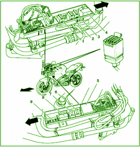
Fuse Panel Layout Diagram Parts: Instrument panel, horn, power socket, instrument panel, Fuel pump, Motronic, Heated handlebar grips, brake light , Rear light, parking light, number palte light, controller for fuel warning lamp or indicator damping.
Read More..

Fuse Box Ford F150 Pickup 4×4 Connector Diagram

Fuse Box Ford F150 Pickup 4×4 Connector Diagram - Here are new post for Fuse Box Ford F150 Pickup 4×4 Connector Diagram.

Fuse Box Ford F150 Pickup 4×4 Connector Diagram


Fuse
Fuse

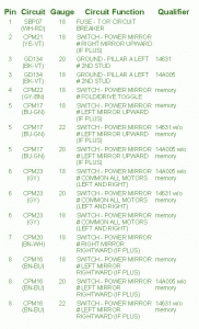
Fuse Panel Layout Diagram Parts: circuit breaker, power mirror, pillar a left, switch, power mirror, right mirror, left mirror, fold/drive toggle.
Read More..

Thursday, September 18, 2014

TDA2002 Amplifier 8W CAR RADIO AUDIO

Simple 8W Audio Amplifier Circuit Diagram with TDA2002. This a Simple 8W Audio Amplifier Circuit Diagram with . The circuit diagram shows that the input signal is blocked in DC across the capacitor of 1μF, then enters the op amp non-inverting input. From the exit take a part of the signal back into the system through the inverting input. The full signal is output continuously removed through 1000μF capacitor and is applied to speaker whose impedance shall be 4 ohms. By placing a speaker of 8 ohms total power obtained is 4 watts. 8W Audio Amplifier Circuit Diagram

Read More..

Explanation Fuse Box Chevrolet Lumina Van 1991 Diagram

Fuse Box Chevrolet Lumina Van 1991 Diagram - This show you about Fuse Box Chevrolet Lumina Van 1991 Diagram.

Fuse Box Chevrolet Lumina Van 1991 Diagram


Fuse
Fuse

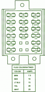
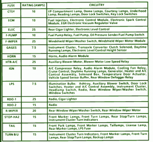
Fuse Panel Layout Diagram Parts: key lock switches, fuel injector, electronic control module, electronic spark control, EGR electronic vacuum regulator valve, cigar lighter, solenoid box, radio, cigar lighter, marker lamp, turn lamp, taillamp, transaxle converter clutch solenoid, daytime running lamp, I/P compartment lamp, dome lamp, courtesy lamp, license lamp, turn indicator, electronic level control, fuel pump relay, oil pressure sender, windshield wiper/washer switch, instrument cluster, temperature door actuator, auxiliary blower switch, door lock switches, electronic level control hight sensor, horn, audio alarm module, auxiliary blower motor, audio alarm module, cooling fan relay, cruise control, generator, heater and A/C control assembly, underhood lamp, reading lamp, door lock switches.
Read More..

Fuse Box Ford 1993 Wagon Diagram

Fuse Box Ford 1993 Wagon Diagram - Here are new post for Fuse Box Ford 1993 Wagon Diagram.

Fuse Box Ford 1993 Wagon Diagram


Fuse
Fuse

Fuse Panel Layout Diagram Parts: running lamp, air bag module, remote keyless entry module, wiper control module, turn lamp, license lamp, anti theft module, warning chime, flash to pass, trailer running lamp relay, trailer B/U lamp relay, memory lock module, instrument panel illumination lamp, power windows, air bag module, power lumbar, hazard lamp, speed control, windshield, wiper motor, Daytime running lamp module, auxiliary battery relay, starting system, transmission control switch, backup lamp, turn lamp, speed control, A/C switch, main light switch, remote jeyless entry, anti theft module, trailer battery charger relay, ignition system, instrument cluster, courtesy lamp switch, power mirror, visor lamp, RABS, instrument panel warning lamp, warning chime, remote keyless entry module, illuminated entry, accessory tap, power door lock, radio memory.
Read More..

Circuit Audio Amplifer with IC 5G37

 Himm.,.,. I just  get this schematic on my mind . This Circuit require voltage supply minimum voltage is 6 Volt and maximum voltage is 12 V . You can  use voltage betwen 6 - 12 volt. Output speaker is mono with power 0,7 watt and impedance 8 Ohm.
See below this Circuit and datasheet IC 5G37 :


Datasheet IC 5G37
Vcc                = 6-12 V
Pout               = 0,7 W
RL                 = 8 Ohm
Ft                   = 40-17 Khz
Icco               = 20 mA
Package         = TABS1-14
Manufactered = China
Read More..

Wednesday, September 17, 2014

Audio Level Adapter

The problem that this circuit is designed to solve appeared when the author was installing a new radio in his Audi A3. The new radio had four outputs for loudspeakers and a line-level output for a subwoofer. However, the A3 as delivered from the factory already has an amplifier for the rear loudspeakers, as well as the pre-installed subwoofer, in the boot space. The original Audi radio therefore has only line-level outputs for the rear loudspeakers. So, to replace the original radio without making other changes to the installed amplification system, he needed to convert the outputs of the new radio corresponding to the rear loudspeakers into line level outputs.

Most of the commercially-available adapters to do this job contain small transformers for galvanic isolation. These introduce phase shifts and create a certain amount of distortion, which the author was keen to minimize. The result is this simple adapter circuit that does not employ a transformer. The outputs of most radios available today have a differential (bridge-type) push-pull output stage. There is thus no ground output, just two outputs per channel with a 180 ° phase difference between them. If the outputs are each connected to a common point via a 100 Ω resistor, that point becomes a virtual ground.

Circuit diagram:

Audio
Audio Level Adapter Circuit Diagram

The ground is relatively stable as (in the stereo case) it has an impedance of 25 Ω. Each output driver is seeing a 200 Ω load: if the amplifier is rated for 50 W output into a 4 Ω load this means that each resistor will dissipate less than 0.5 W. Hence 1 W rated resistors will be more than adequate, especially in view of the fact that typical music has a crest factor of at least five. Even a small DC offset from the virtual ground is not a problem, as most modern amplifiers feature differential inputs or at least allow the ground connection of an input to float. To reduce the signals to line level, each has to be connected to a potential divider: a multi-turn preset potentiometer is ideal.

The author used a linear 10 kΩ trimmer to reduce the output voltage level from up to about 12 Vpp to around 2 V to 3 V. This latter level is suitable for the input to a power amplifier. An appropriate trimmer setting can be found by ear, adjusting the volume of the rear speakers for the desired balance. There is no need for a printed circuit board for this project. The 1 W resistors can be soldered directly to the connections of the multi-turn presets, and so the whole thing can be assembled ‘in the air’ and shrouded in heat-shrink tubing. The circuit can then be tucked away in the space behind the radio itself.
Read More..

Fuse Box Toyota 1990 4runner Junction Diagram

Fuse Box Toyota 1990 4runner Junction Diagram - Here are new post for Fuse Box Toyota 1990 4runner Junction Diagram.

Fuse Box Toyota 1990 4runner Junction Diagram


Fuse
Fuse

Fuse Panel Layout Diagram Parts: engine, ignition coil, tail light, wiper washer, gauge, stop lamp, radio, cigar lighter, turn lamp, ECU ignition, defogger relay, taillight control relay, starter or back up relay, power window.
Read More..

Fuse Box Ford 2001 Escape Diagram

Fuse Box Ford 2001 Escape Diagram - Here are new post for Fuse Box Ford 2001 Escape Diagram.

Fuse Box Ford 2001 Escape Diagram


Fuse
Fuse

Fuse Panel Layout Diagram Parts: canister vent control solenoid, blower relay, rear defrost relay, pressure switch to PCM, rear wiper motor, rear washer motor, rear wiper relay.
Read More..

12V battery indicator level


indicatorThe following sequence is useful to show the battery voltage (battery) 12 volts. Voltage level is shown with four lights led. To facilitate the reading of the led is arranged in a vertical array. Led top three chosen by the green LED while the lowest is selected the color red. If the battery voltage continues to decline (because of usage), the Led-Led will turn off sequentially from the top to the bottom.

Until if battery voltage is below 11.83 volts then only the red LED that lights up which means that the charge batteries are empty. Even this red Led will die if the stress continues to drop to below 11.5 volts. The working principle of this circuit is a comparison of battery voltage with a reference voltage.

Schematic Battery level indicator
indicator

Read More..

Fuse Box 1991 BMW 325i Diagram

Fuse Box 1991 BMW 325i Diagram - Here are new post for Fuse Box 1991 BMW 325i Diagram.

Fuse Box 1991 BMW 325i Diagram


Fuse
Fuse

Fuse Panel Layout Diagram Parts: Headlights, High beam indicator, Headlights, Auxiliary fan, Lights/Turn hazard warning, Active check control, Glove box light, Electro-mechanical convertible top, Wiper/washer, Stop lights/cruise control, Active check control, Antilock braking system, Cruise control, Map reading light, Rear defogger, Injection electronics, Ignition key warning/seatbelt warning, back-up lights, Tachometer/Fuel economy gauges, Injection electronics, Brake warning system, Cruise control, Injection electronics, adio, speedometer, on-board computer, Headlights, Heated seats, Power windows, Auxiliary fan, Interior Lights, Power mirrors, Heater/Air conditioning, Auxiliary fan.
Read More..

Tuesday, September 16, 2014

90 Watt Switching Power Supply

90
Switching Power Supply in this article are able to supply power 90 Watt. Switching Power Supply series is built directly from an AC network system using special IC MC33374 switching power supply in the form of High Voltage Power Switching Regulator and with external components to the other.


IC MC33374 IC is a switching power supply designed to operate with an AC voltage source and works as a power switching converter with flyback technique. Switching Power Supply Series has a 15 volt DC output with current up to 6 Ampere.

90
90 Watt Switching Power Supply Schematic

Series 90 Watt Switching Power Supply works by menyearahkan AC source is then used to activate the converter MC33374 system. The output of transformer switching converter MC33374 searahkan again later on as a DC voltage supply to be used for electronic devices.
Read More..

Explanation Fuse Box Chevrolet Blazer Underhood 1997 Diagram

Fuse Box Chevrolet Blazer Underhood 1997 Diagram - This show you about Fuse Box Chevrolet Blazer Underhood 1997 Diagram.

Fuse Box Chevrolet Blazer Underhood 1997 Diagram


Fuse
Fuse

Fuse Panel Layout Diagram Parts: battery, ABS system, ignition system, park lamp, HVAC, rear defogger, daytime running lamp, ECM system, headlamp, power window, amplifier, stop lamp, heated seat, horn, turn lamp.
Read More..

60W Inverter using transistors

Here is the circuit diagram of a fully transistorized inverter that can drive up to 60W loads. Transistors Q1 and Q2 forms a 50Hz astable multivibrator. The output from the collector of Q2 is connected to the input of the Darlington pair formed by Q3 and Q4.Similarly the output of Q1 is coupled to the input of the pair Q5 and Q6. The output from the Darlington pairs drive the final output transistors Q7 and Q8 which are wired in the push pull configuration to drive the output transformer.

Circuit diagram :

60W inverter using transistors Circuit Diagram

Notes.

  • The circuit can be assembled on a vero board.
  • T1 can be a 230V primary to 9-0-9V, 6A secondary transformer.
  • Transistors Q4, Q6, Q7 and Q8 must be fitted with heat sinks.
  • Use a 12V, 7Ah battery for powering the inverter.
  • Slight adjustments can be made on the value of R3 and R4 to get exact 50Hz output.

Read More..

Maximite Stepper Motor Interface Wiring diagram Schematic

This simple schema and program listing allows the Maximite microcomputer (SILICON CHIP, March-May 2011) to control a stepper motor. It could be expanded to allow for the control of multiple motors, with four of the Maximite’s external I/O pins used to control each motor with identical driver diagram. A ULN2003 Darlington transistor array (IC1) switches current through the stepper motor’s two windings in either direction. When one of the four Maximite output pins (8, 12, 16 & 20, corresponding to I/Os 19, 17, 15 & 13) goes high, the corresponding output pin on IC1 goes low, sinking current through a motor winding. Conversely, when these pins are high, the corresponding Darlington transistor is off and so no current flows through that portion of the winding.

Maximite Stepper Motor Interface Circuit Diagram


Maximite
The centre tap of each motor winding is connected to a current source comprising PNP Darlington transistor Q1 and some resistors. The maximum current is determined by the resistive divider driving its high-impedance base, setting the base voltage to around 9.1V when it is fully on. By adding Q1’s base-emitter voltage (1.4V at 0.5A, as per the data sheet) we can determine that there will be around 1.5V across the 3.3O resistor (12V - 10.5V), resulting in a current of 1.5V ÷ 3.3O = ~450mA. Transistor Q1 must be fitted with a medium-sized flag heatsink (Jaycar HH8504, Altronics H0637) or larger to handle its maximum dissipation of (10.5V - 4.9V) x 450mA = 2.5W.

When one of the Darlington transistors switches off and current flow through the corresponding motor winding ceases, the inductive winding generates a back-EMF current which causes the voltage across that winding to spike. IC1 has internal “free-wheeling” diodes from each output to the COM pin, which is connected to the +12V supply. The back-EMF current flows back into the power supply and the voltage spikes are clamped at about 12.7V, so that the Darlington transistors do not suffer collector reverse breakdown, which might damage them.

A 470µF capacitor provides supply bypassing for the motor while a 47kO pull-up resistor and toggle switch/pushbutton S1 drives input pin 9 of the Maximite, allowing manual control of the motor direction. Table 1 shows the sequence in which the output pins are driven to turn the motor forward; the steps are run backwards for reverse operation. The delay between the steps determines the speed at which the motor rotates. The source code of the sample program is available for download from the SILICON CHIP website (maximite_stepper_motor.bas). 
Source by : Streampowers
Read More..

Fuse Box Ford 1997 Escort Under Hood Diagram

Fuse Box Ford 1997 Escort Under Hood Diagram - Here are new post for Fuse Box Ford 1997 Escort Under Hood Diagram.

Fuse Box Ford 1997 Escort Under Hood Diagram


Fuse
Fuse

Fuse Panel Layout Diagram Parts: headlamp relay, powertrain control module, fuel pump relay, PCM power relay, fuel pump relay, octane adjust plug.speed control amplifier, instrument panel dimming module, electrnic flasher, blower motor relay.
Read More..

Monday, September 15, 2014

Mercedes Explanation Fuse Box Year 2000 SL500 Diagram

Fuse Box Mercedes 2000 SL500 Diagram - Below is Fuse Box Mercedes 2000 SL500 Diagram.

Fuse Box Mercedes 2000 SL500 Diagram


Fuse
Fuse

Fuse Panel Layout Diagram Parts: exterior lamp, combination relay, fuse and relay holder, gasket, fuse box cover, screw, relay box cover.
Read More..

XR 13600Universal active filter

The circuit as shown gives the bandpass operation the transfer function calculated from FBP(s) = where = 1 + s/Qo>0 + s2/w02. The cut-off frequency, 0, and the Q-factor are given by 0 = g/C and Q = gR/2 where g is the transconductance at room temperature. Interchanging the capacitor C with the resistor R at the input of the circuit high-pass operation is obtained. A low-pass filter is obtained by applying two parallel connections ctf R and C as shown in Fig. 2. The low-pass operation may be much improved with the circuit as given in Fig. 3.


Read More..

Simple Medium Wave Modulator

If you insist on using a valve radio and listening to medium-wave stations, you have a problem: the existing broadcasters have only a limited number of records. Here there’s only one remedy, which is to build your own medium-wave transmitter. After that, you can play your own CDs via the radio.

The transmitter frequency is stabilised using a 976-kHz ceramic resonator taken from a TV remote control unit. Fine tuning is provided by the trimmer capacitor. If there’s another station in the background, which will probably be weak, you can tune it to a heterodyne null, such as 981 kHz. As an operator of a medium-wave transmitter, that’s your obligation with respect to the frequency allocations. And that’s despite the fact that the range of the transmitter is quite modest. The small ferrite coil in the transmitter couples directly into the ferrite rod antenna in the radio.

Medium-Wave Modulator Circuit Diagram


Medium-Wave-Modulator-Circuit-Diagram


The modulator is designed as an emitter follower that modulates the supply voltage of the output amplifier. As the medium-wave band is still mono, the two input channels are merged. The potentiometer can be adjusted to obtain the least distortion and the best sound. The RF amplifier stage has intentionally been kept modest to prevent any undesired radiation. The quality of the output signal can also be checked using an oscilloscope. Clean amplitude modulation should be clearly visible. 

The medium-wave modulator can simply be placed on top of the radio. A signal from a CD player or other source can be fed in via a cable. Now you have a new, strong station on the radio in the medium-wave band, which is distinguished by good sound quality and the fact that it always plays what you want to hear.

Author: Burkhard Kainka - Copyright: Elektor
Read More..

Simple 3000 Watts UPS Wiring diagram Schematic

How to Build Simple 3000 Watts UPS Circuit Diagram. This is a Simple 3000 Watts UPS Circuit Diagram

Simple 3000 Watts UPS Circuit Diagram

Simple

Read More..

Sunday, September 14, 2014

Mercedes Explanation Fuse Box Year Benz 1988 E190 Diagram

Fuse Box Mercedes Benz 1988 E190 Diagram - Below is Fuse Box Mercedes Benz 1988 E190 Diagram.

Fuse Box Mercedes Benz 1988 E190 Diagram


Fuse
Fuse

Fuse Panel Layout Diagram Parts: combination relay, heatable rear window, turn signal, wiper, relay window opener, air conditioning, overvoltage, protection.
Read More..

Power Amplifier circuit with IC TDA1904

This circuit is circuit use the IC TDA1904 and IC TDA1905.
See schmatic below :

Technical instruction :
Minimum supply voltage   : 4 volts
Maximum supply voltage  : 20 volts
Minimum currents             : 40 mA
Input can with                    : CD , Tuner , Tape , Preamp Mic , Media Player device.
Maximum Power Output   : 10Watts
Minimum Power  Output   : 4 Watts
Impedance Speakers          : 4 Ohms
Read More..

High temperature protector with IC 3584

IC 3584 has thermal protection or voltage automatically shutdown when the temperature at IC exceed 150 degrees or more. You can operate this circuit at the transistor or IC heatsing, if a transistor or IC had exceeded the limit of the heat circuit automatically shutdown.

How to use a thermal shutdown circuit above that is first given a circuit of voltage V+,V-,and ground , the given a voltage Vin to be created automatically shutdown if the temperature is high , and the output is inserted in the circuit of an amplifier or other. Then IC embedded in the heatsing or case, which if too hot will shutdown alone. If the circuit already decided voltage, the voltage will re-connect if the temperature returns to normal.
Read More..