Tuesday, August 12, 2014
Snubber Triggering scr series Wiring diagram Schematic
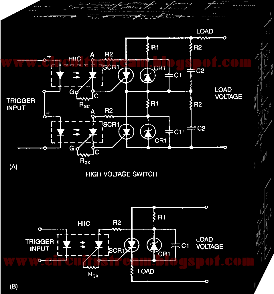
This is a simple switching Snubber Triggering scr series Circuit Diagram. A simple snubber uses a small resistor (R) in series with a small capacitor (C). This combination can be used to suppress the rapid rise in voltage across a thyristor, preventing the erroneous turn-on of the thyristor; it does this by limiting the rate of rise in voltage (dV/dt) across the thyristor to a value which will not trigger it. Snubber schema R2C2, as shown, might be necessary since Rl and Cl are tailored for optimized triggering and not for dV!dt protection. Fiber-optic pairs can be used with discrete SCRs to switch thousands of volts.
Snubber Triggering scr series Circuit Diagram

A photon coupler with a transistor output will limit the trigger-pulse amplitude and rise time because of CTR and saturation effects. Using the HllCl, the rise time of the input pulse to the photon coupler is not critical, and its amplitude is limited only by lite HllCl turn-on sensitivity. The load can also be connected to the cathode as illustrated in Fig. 67-3B.
Subscribe to:
Post Comments (Atom)
No comments:
Post a Comment
Note: Only a member of this blog may post a comment.