Showing posts with label automatic. Show all posts
Showing posts with label automatic. Show all posts
Wednesday, November 12, 2014
Automatic Battery Charger
Normally, chargers available in the market do not have any sort of control except for a ro-tary switch that can select different tap-pings on a rheostat, to vary the charging current. This type of control is not adequate because of the irregular fluctuations in the mains supply, rendering the control ineffective. A simple circuit intended for automatic charging of lead-acid batteries is presented here. It is flexible enough to be used for large capacity inverter batteries. Only the rating of transformer and power transistor needs to be increased.
Circuit diagram :

Circuit diagram :
Automatic Battery Charger
The circuit has been basically designed for a car battery (about 40 Ah rating), which could be used for lighting two 40W tube lights. The circuit includes Schmitt trigger relay driver,float charger,and battery voltage monitor sections. The Schmitt trigger is incorporated to avoid relay chattering. It is designed for a window of about 1V. During charging, when the battery voltage increases be-yond 13.64V, the relay cuts off and the float charging section continues to work.
When battery voltage goes below 11.66V, the relay is turned on and direct (fast) charging of the battery takes place at around 3A. In the Schmitt trigger circuit, resistors R1 and R2 are used as a simple voltage divider (divide-by-2) to provide battery voltage sample to the inverting input terminal of IC1. The non-invert-ing input terminal of IC1 is used for reference input derived from the output of IC2 (7806), using the potentiometer arrangement of resistors R3 (18 kilo-ohm) and R4 (1 kilo-ohm).
LED1 is connected across relay to indicate fast charging mode. Diodes D3 and D6 in the common leads of IC2 and IC3 respectively provide added protecion to the regulators. The float charging section, comprising regulator 7812, transistors T3 and T4, and few other discrete components, becomes active when the battery volt-age goes above 13.64V (such that the relay RL1 is deenergised). In the energised state of the relay, the emitter and collector of transistor T4 remain shorted, and hence the float charger is ineffective and direct charging of battery takes place.
The reference terminal of regulator (IC3) is kept at 3.9V using LED2, LED3, and diode D6 in the common lead of IC3 to obtain the required regulated output (15.9V), in excess of its rated output, which is needed for proper operation of the circuit. This output voltage is fed to the base of transistor T3 (BC548), which along with transistor T4 (2N3055) forms a Darlington pair. You get 14.5V output at the emitter of transistor T4, but because of a drop in diode D7 you effectively get 13.8V at the positive terminal of the battery.When Schmitt trigger switches ‘on’ relay RL1, charging is at high current rate (boost mode). The fast charging path, starting from transformer X2, comprises diode D5, N/O contacts of relay RL1, and diode D7.
The circuit built around IC4 and IC5 is the voltage monitoring section that provides visual display of battery voltage level in bar graph like fashion. Regulator 7805 is used for generating reference voltage. Preset VR1 (20 kilo-ohm) can be used to adjust voltage levels as indicated in the circuit. Here also a pot meter arrangement using resistors R7, R8, and R9 is used as ‘divide by 3’ circuit to sample the battery voltage. When voltage is below 10V, the buzzer sounds to indicate that the safe dis-charge limit has been exceeded.

Saturday, November 8, 2014
SP Semi Automatic Paintbrush
Got a replacement InkShield and progressing to build an Open hardware project? Then why not strive creating the Semi-Automatic Paintbrush. browse on to grasp a lot of concerning this.

Any work of art are often copied using this and therefore the elements that are needed to form this is often listed below:
IR camera
InkShield
Ink cartridge
IR LED.
The software thats run on a desktop for this purpose is understood as paintbrush.py. The software plays the role of mapping the camera focus with the co-ordinate system of the canvas. Four LEDs are placed at every corner of the canvas and therefore the mapping is calibrated by hitting a key when needed.
The region of the image is captured by tracking the motion of the LEDs. the mandatory commands are send to an Arduino with the InkShield by means that of a script written for this purpose. The script tells the arduino that nozzle to fireplace and additionally the grey level that must be achieved by the firing nozzle. so as to avoid flooding, the painted areas are tracked.
IR camera
InkShield
Ink cartridge
IR LED.
The software thats run on a desktop for this purpose is understood as paintbrush.py. The software plays the role of mapping the camera focus with the co-ordinate system of the canvas. Four LEDs are placed at every corner of the canvas and therefore the mapping is calibrated by hitting a key when needed.
The region of the image is captured by tracking the motion of the LEDs. the mandatory commands are send to an Arduino with the InkShield by means that of a script written for this purpose. The script tells the arduino that nozzle to fireplace and additionally the grey level that must be achieved by the firing nozzle. so as to avoid flooding, the painted areas are tracked.
Sunday, September 21, 2014
Automatic Load Sensing Power Switch
This circuit will automatically switch on several mains-powered "slave" loads when a "master" load is turned on. For example, it will switch on the amplifier and CD player in a stereo system when the receiver is turned on. It works by sensing the current draw of the "master" device through a low value high wattage resistor using a comparator. The output of that comparator then switches on the "slave" relay. The circuit can be built into a power bar, extension cord or power center to provide a convenient set of "smart" outlets that switch on when the master appliance is powered (turn on the computer monitor and the computer, printer and other peripherals come on as well).
Automatic Load Sensing Power Switch Circuit diagram

Parts List
Notes
Automatic Load Sensing Power Switch Circuit diagram

| C1, C3 | 2 | 10uF 35V Electrolytic Capacitor | ||
| C2 | 1 | 1uF 35V Electrolytic Capacitor | ||
| R1 | 1 | 0.1 Ohm 10W Resistor | ||
| R2 | 1 | 27K 1/2W Resistor | ||
| R3, R4 | 1 | 1K 1/4W Resistor | ||
| R5 | 1 | 470K 1/4W Resistor | ||
| R6 | 1 | 4.7K 1/2W Resistor | ||
| R7 | 1 | 10K 1/4W Resistor | ||
| D1, D2, D4 | 3 | 1N4004 Rectifier Diode | ||
| D3 | 1 | 1N4744 15V 1 Watt Zener Diode | ||
| U1 | 1 | LM358N Dual Op Amp IC | ||
| Q1 | 1 | 2N3904 NPN Transistor | ||
| K1 | 1 | Relay, 12VDC Coil, 120VAC 10A Contacts | ||
| S1 | 1 | SPST Switch 120AVC, 10A | ||
| MISC | 1 | Board, Wire, Socket For U1, Case, Mains Plug, Socket |
Notes
- This circuit is designed for 120V operation. For 240V operation, resistors R2 and R6 will need to be changed.
- A maximum of 5A can be used as the master unless the wattage of R1 is increased S1 provides a manual bypass switch.
- THis circuit is not isolated from the mains supply. Because of this, you must exercise extreme caution when working around the circuit if it is plugged in.
Sunday, August 31, 2014
SP Semi Automatic Paintbrush
Got a replacement InkShield and progressing to build an Open hardware project? Then why not strive creating the Semi-Automatic Paintbrush. browse on to grasp a lot of concerning this.
Any work of art are often copied using this and therefore the elements that are needed to form this is often listed below:
IR camera
InkShield
Ink cartridge
IR LED.
The software thats run on a desktop for this purpose is understood as paintbrush.py. The software plays the role of mapping the camera focus with the co-ordinate system of the canvas. Four LEDs are placed at every corner of the canvas and therefore the mapping is calibrated by hitting a key when needed.
The region of the image is captured by tracking the motion of the LEDs. the mandatory commands are send to an Arduino with the InkShield by means that of a script written for this purpose. The script tells the arduino that nozzle to fireplace and additionally the grey level that must be achieved by the firing nozzle. so as to avoid flooding, the painted areas are tracked.
Thats all its. The paintbrush is complete. this is often a lot of of a fun-based project and may be tired some spare time using the elements mentioned earlier. the desired script is out there on github. The InkShield library employed by the
Tuesday, August 12, 2014
Automatic Headlight Brightness Switch Wiring diagram Schematic
Going by car the highway with your high-beam headlights can actually increase your visibility, but can be a blinding hazard for other drivers. This easy schema can be connected into your headlight swap to provide automatic swaping between high and reduced beam headlights when there is oncoming traffic. It does this by feeling the lights of that traffic. In this way, you can propel securely with your high-beams on without blinding other drivers.
Automatic Headlight Brightness Switch Circuit Diagram
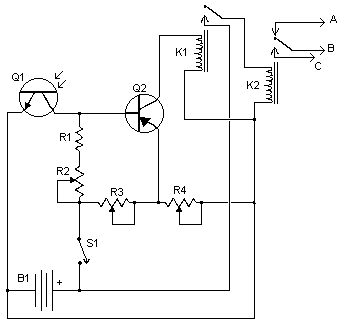
- Q1 should me mounted in such a way so it points toward the front of the car with a clear line of site.
- Suitable places are on the dashboard, in the front grill, etc.
- Adjust all the pots for proper response by testing on a deserted road.
- S1 enables and disables the schema.B1 is, obviously, in the car already.
- Before you try to connect this schema, get a wiring diagram for your car.
- Some auto manufacturers do weird things with wiring.
- Connection A goes to the high beam schema, B goes to the headlight switch common and C connects to the low beam schema.
| R1 | 1 | 5K 1/4W Resistor | |
| R2, R3, R4 | 3 | 5K Pot | |
| Q1 | 1 | NPN Phototransistor | |
| Q2 | 1 | 2N3906 PNP Transistor | |
| K1 | 1 | Low Current 12V SPST Relay | |
| K2 | 1 | High Current 12V SPDT Relay | |
| S1 | 1 | SPST Switch | |
| B1 | 1 | Car Battery | |
| MISC | 1 | Case, wire, board, knobs for pots |
Subscribe to:
Posts (Atom)