Showing posts with label diode. Show all posts
Showing posts with label diode. Show all posts
Thursday, October 2, 2014
Zero Drop Diode Circuit for Solar Charger Application
Any diode-based circuit that safeguards against supply polarity reversal brings about a certain voltage drop. The following post shows a zero drop diode equivalent circuit which can specifically become useful for solar charger applications.
Solar panels as we all know may heavily depend on the position of the sun and its rays intensity. Under overcast conditions the solar panel strength also deteriorates and its voltage drops. A diode is normally associated with solar panels for preventing accidental reverse connection, however a rectifier diode or even other forms of diodes also drop some voltage across them which might become crucial during bad sun light conditions.
The discussed circuit of a zero drop diode circuit effectively handles the above situation.
Additionally, in case relatively higher currents are associated, the employment of an applicable diode, and its dissipation, can pose problems.
This circuit employs a relay contact to disconnect the positive supply whenever the input voltage is rendered the wrong polarity. The coil voltage of the relay can be selected to be lower than the input voltage, since Re is triggered within a few milliseconds, and subsequently acquires the correct coil voltage through T1-D1.
As the sustaining voltage of a relay is ususally below than the switching voltage, D2 can be calculated such that the relay triggers optimally with a lowest of zener current consumed from the supply.

Solar panels as we all know may heavily depend on the position of the sun and its rays intensity. Under overcast conditions the solar panel strength also deteriorates and its voltage drops. A diode is normally associated with solar panels for preventing accidental reverse connection, however a rectifier diode or even other forms of diodes also drop some voltage across them which might become crucial during bad sun light conditions.
The discussed circuit of a zero drop diode circuit effectively handles the above situation.
Additionally, in case relatively higher currents are associated, the employment of an applicable diode, and its dissipation, can pose problems.
This circuit employs a relay contact to disconnect the positive supply whenever the input voltage is rendered the wrong polarity. The coil voltage of the relay can be selected to be lower than the input voltage, since Re is triggered within a few milliseconds, and subsequently acquires the correct coil voltage through T1-D1.
As the sustaining voltage of a relay is ususally below than the switching voltage, D2 can be calculated such that the relay triggers optimally with a lowest of zener current consumed from the supply.

Monday, August 11, 2014
Zener Diode Increase Regulator Output Wiring diagram Schematic
A zener diode in the ground lead of a fixed pnp regulator varies the voltage output of that device without a significant sacrifice in regulation. The technique also allows the regulator to operate with output voltages beyond its rated limit.
Zener Diode Increase Regulator Output Circuit Diagram
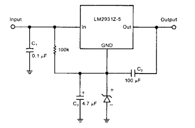
Zener Diode Increase Regulator Output Circuit Diagram
Subscribe to:
Posts (Atom)