Wednesday, November 19, 2014
6 12 Volt audio amplifier

The above is an amplifier circuit using supply voltages from 6 volts DC to 12 Volt DC. Power output of the amplifier is quite low with only 1 Watt 8 ohm impedance. You can apply this to the audio signal amplifiers that require strengthening are not so large as in the pocket radio.Part List :
R1 = 100K
R2 = 39R
R3 = 100R
C1 = 100nF
C2 = 100uF
C3 = 100uF
C4 = 100uF
C5 = 470uF
C6 = 100nF
C7 = 68pF
C8 = 1nF
C9 = 47uF
IC = SFC2790C

Simple LED Emergency Light Circuit

This LED emergency light project is simple, cheap and easy to build. The circuit do the charging of the battery and when the main source is not available such as in brownouts, the white LEDs automatically turn on.
Initially, the voltage output from 220V to 12V converter is fed to the input of LM317 regulator. Then this voltage is regulated down to 7.37V using 240 ohms and 1.2K resistor combination (see LM317 Calculator).
At this instant, the battery is in charging mode and the transistor Q1 is off. Indicator LED serves two purpose, one primarily is to give us idea that the battery is charging and another is to ensure that the Q1 is off.
During brownouts, the transistor Q1 is on and delivers current to 16 white LED of about 20mA each, thus a fully charged battery (6V/4.5Ah) can last up to 14 hours.
The charger has no built in over-current control but still it protects the battery from overcharging since the charging voltage is set only to 7.4V.
Project materials:
1pc - transformer - 220V to 12V-0-12V , center tap 12VA
16pc - 120 ohms resistor 1/4 W
16pc - white LED min 3V@30mA
1pc - red LED
1pc - 1000uF/25V electrolytic capacitor
3pc - 1N4001 diode
1pc - LM317 regulator
1pc - 1.5K resistor 1/4W
1pc - 240 ohms resistor 1/4W
1pc - 1.2k resistor 1/4W
1pc - 9012 pnp transistor or any of much higher capacity
1pc - 6V 4.5ah battery
1500W Stereo Power Amplifier Schematic
Circuit Power Amplifier has a power output of up to 1500W RMS power amplifier circuit is often used to power sound systems keperlun for outdor. In the final image can be seen a series of power amplifiers using 10 sets of power transistors for the ending.
This power amplifier circuit using a transistor amplifier from the front, signal splitter, driver and power amplifier. Current consumption required is quite large power amplifier that is 15-20 A 1500W power amplifier circuits for this. Supply voltage needed by the power of this amplifier is the optimal working order symmetrical 130VDC (130VDC-130VDC ground). 1500W amplifier circuit below is a picture series of mono, stereo if you want to make it necessary to make two copies of the circuit. For more details can be viewed directly image the following 1500W power amplifier circuit.
The series of High Power Amplifier 1500W With Transistor
 |
| Click Image to view larger |
In the above series of power amplifer 1500W is equipped to control a DC Offset function to set the power amplifier is turned on at the moment and with no input signal then the output should be 0VDC. Then also equipped with a flow regulator to the power amplifier bias. Final part of this power amplifier requires adequate cooling to absorb the heat generated. Power amplifier is not equipped with a speaker protector, therefore it is necessary diapsang protector on the speaker output so that when the power amplifier is not the case turned on the beat to the speaker that can damage the speaker.
Tuesday, November 18, 2014
120W Stereo Amplifier using STK4241V
Here is a circuit 120 watt stereo amplifier using STK4241V. The MAX9710 a stereo audio power amplifier capable of delivering 2 x 120 W of the IC to put loads of 8 ohms. MAX9710 can be operated from ± 32V single power supply of ± 54V.
This amplifier circuit is ideal for audio devices for home supply. STK4241V amplifier specifications might lead one to believe that you can use supply voltages of ± 78V. With zero input signal (and therefore no way out) I could, but I would not recommend anything better than ± 45V 8-ohm loads, if expected, although ± 54V will be fine if you can provide a good heat sink.
This amplifier circuit is ideal for audio devices for home supply. STK4241V amplifier specifications might lead one to believe that you can use supply voltages of ± 78V. With zero input signal (and therefore no way out) I could, but I would not recommend anything better than ± 45V 8-ohm loads, if expected, although ± 54V will be fine if you can provide a good heat sink.
Switch With Relay Schematic
Light Switch With Relay is a series of electronic switches that are controlled by a series of light received. Light Switch With Relay circuit can be used to control lighting automatically, so the lights can automatically turn on when the room light or the region began to decrease. Limit of light used to activate the electronic switch in the circuit Light Relay Switch With This can be set via the potentiometer P1. P1 setting is basically a light reception sensitivity settings. Light Switch With Relay circuit uses the LDR as the light sensor and an IC 741 as a comparator and reference voltage sensor, relay driver transistor Q1 as as an electronic switch. A complete range of Light Switch With Relay is as follows.
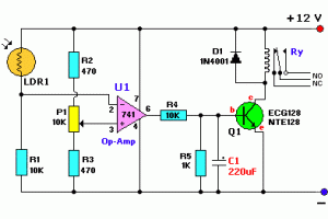
Circuit Light Relay Switch With diats a light switch that will be active when the sensor does not receive light, if you want to turn the tables (the active switch when the sensor receives light) it can be done by reversing the position between the LDR and R1. Diodan D1 serves to avoid the effects of EMF or sparking of the relay coil. The circuit is simple and easy to make, I hope to provide ideas and descriptions in the manufacture of a controlled light switch. Hopefully useful.
Microphone Pre Amplifier 9 12Volt Discrete
This is a microphone pre-amplifier ambit that use detached components. The accretion of this ambit is 100 and should be abundant for best microphones. It is set by the arrangement of the 10k resistor to the 100R. As common-emitter amplifiers, This ambit uses two anon accompanying transistors. Here is the schematic diagram of circuit:
Please note that this ambit has no bent voltage source, so you can’t use with condenser blazon microphones. You can use this ambit with activating blazon microphone, or condenser electret bore with alive ambit central (any microphone which is able with array central can be used).
Doubler Digital Frequency circuit
Doubler Digital Frequency circuit includes a simple and easy to understand. Digital Frequency Doubler circuit application contained in the system electronics such as audio-producing organ, or keyboard. The function of this series Digital Frequency Doubler for multiplying two input frequencies.
The process of multiplying 2 on scales in an organ in principle is like this series Digital Frequency Doubler. Example of rising to a ringing tone DO RE then electronically technique in it is by multiplying the two frequency bands such as this series Digital Frequency Doubler.
 |
| Digital Frequency Doubler. |
Subscribe to:
Posts (Atom)